The D Plane is a term you may have come across in golfing forums or instruction videos online. It’s a concept known for being difficult to understand, and hard to find a thorough, yet simple explanation of. I hope by the end of this chapter however, you will know exactly what the D Plane is.
The D Plane is a term first coined by the physicist Theodore Jorgensen in his book The Physics of Golf. Professor Jorgensen investigated the golf swing using scientific models and equations to understand the frustrating game we know and love. When studying the flight of the ball, and asking which factors cause the ball to move the way it does, Jorgensen quantified the cause: the D Plane.
The name itself promotes some uncertainty, but rest assured clarification is at hand... The “D” simply stands for “Descriptive”. The Descriptive Plane does exactly what the name suggests; it’s a plane that describes something. In this case, it describes certain conditions at impact and the flight of the golf ball.
Before we go into detail on the D Plane, I make no apologies for going right back to basics and explaining what a plane actually is. There’s little point jumping in at the deep end and not understanding the geometry behind it!
A plane is flat, two-dimensional surface, much like a sheet of paper. For a plane to exist, it requires two intersecting vectors. A vector, in layman’s terms, is a quantity of something that also has a direction. For our sheet of paper, its vectors are its width and height (but no depth, that’s negligible and we’ll pretend it’s a true two-dimensional surface). The width and height of the sheet of paper have a quantity which we could measure using a ruler. The width and height also have directions. Holding a sheet of paper up in front of you, you can say the width vector starts at the bottom left corner of the sheet, and travels in a straight line from left to right, ending at the right bottom corner. The height vector again begins at the bottom left corner and travels upwards in a straight line, from bottom to top, ending at the top left corner of the sheet of paper.
As well as having two vectors, our plane, or sheet of paper, needs another element to exist; for those two vectors to connect at some point. Otherwise we have no plane, just two unrelated vectors. When holding our sheet of paper in front of us, we can see the width and height vectors of the paper are connected at the bottom left corner.
So to sum up: a plane is made up of two lines, pointing in different directions, joining at some point. The plane is the flat, two-dimensional space between those two lines.
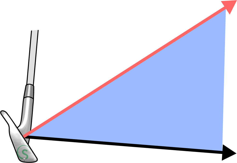
With our understanding of what a plane is, let’s move on to the D Plane! The D Plane occurs at impact. At this time there are two vectors, two straight lines, we can measure. They are; the direction the clubhead is traveling, and the direction the clubface is pointing
Click on the below links to take a look at the vectors making up the D Plane.
Normal to Clubface
Clubhead Path
Normal to Clubface
Clubhead Path
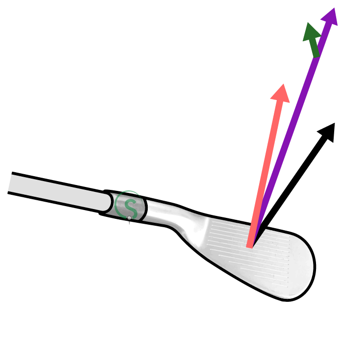
Now we understand the two vectors creating the D Plane, we can look at the ball’s flight. This is represented by two lines on the D Plane diagram. The first is the purple line, which shows the ball’s initial flight. This line will be found on the two-dimensional plane between the normal of the clubface, and the clubhead’s path through impact.
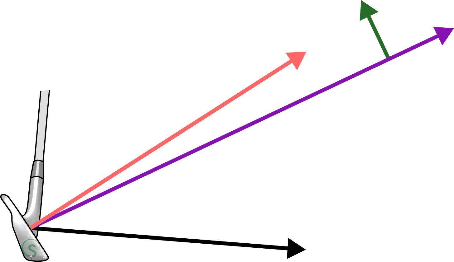
The PGA’s “Ball Flight Laws” teach the initial flight of the ball is where the clubface is pointing. This isn’t strictly true as you’ll see the purple line is slightly below the normal to the clubface. This is because the collision between the club and ball is “inelastic”,(1) meaning there is loss of kinetic energy during impact. This loss of energy is described by a concept known as the “coefficient of restitution”.(2) Put simply, the less energy lost during impact, the closer to the normal of the clubface, and further, the ball will fly.
The second line describing the ball flight is the green one, pointing upwards from the initial direction flight line at a right angle to it. This line represents the direction of lift on the ball, due to the difference in air pressure around the spinning ball.(3)
This line, which lays flat on the D Plane is the most important in describing why the ball curves the way it does during its flight. The green line points towards the area of low air pressure around the ball, the direction the ball will curve towards.
Now understanding how the D Plane is created and what the lines represent, let’s look at a few examples of different D Planes and the ball flights they describe.
1
2
3
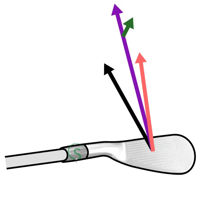
The D Plane labeled '1' shows the normal to the clubface pointing slightly left of target (target being due north in the diagram), and the clubhead path further left of target. The ball will therefore begin its flight left of target, but then curve to the right, as the D Plane is tilted to the right. The amount the D Plane is tilted determines how much the ball will curve left or right. How much the D Plane tilts is due to the difference in direction of the normal to the clubface and the clubhead path when viewed from above.
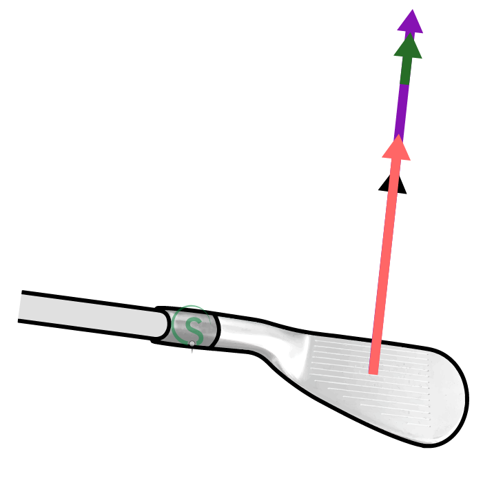
You’ll notice that D Plane '2' shows the normal to the clubface and the clubhead path both pointing in the same direction: to the right of target. This means the D Plane itself is not tilted left or right (it’s vertical) and so the direction of lift on the ball is straight upwards. This D Plane describes the flight of a push. Finally, D Plane '3' shows a push draw flight. The normal to the clubface points right of target and the clubhead path more so. This causes the D Plane to tilt to the left.
That pretty much sums up the D Plane. I don’t really agree with this concept for a couple of reasons, as you’ll discover in the next chapter.
Next Topic